The functional description of the fuel system comprises the components:
The fuel tank installed in front of the rear axle (saddle design) consists of a left-hand and right-hand chamber.
When refuelling, first the right-hand chamber followed by the left-hand chamber are filled via the filler pipe and a formed hose. A non-return valve is fitted in the fuel tank at the connection for the formed hose from the filler pipe.
The part of the filler pipe comprising the filler ventilation line and the tank filler neck is one part and forms the upper half of the filler pipe. A formed hose provides the connection from the upper half of the filler pipe to the fuel tank. It is connected with a filler neck at the fuel tank. A non-return valve is fitted at the end beneath the tank.
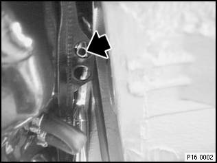
The connection for the filler ventilation of both tank halves is located on the upper right of the fuel tank ahead of the cover for the fuel tank sensor with the fuel pump. It is connected to the section of the filler ventilation line fitted to the filler pipe.
The non-return valve at the connection coupling for the formed hose from the filler pipe is located inside the fuel tank. It prevents fuel from flowing out in the event of an accident.
Particular care must be taken when checking to ensure that the non-return valve moves smoothly.
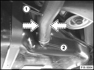
In order to check the movement of the non-return valve, the formed hose can be temporarily pressed together at the point indicated by the arrows. In this way, the fuel is forced into the tank and flows back again. The non-return valve can be heard to move as the result of this flow of fuel.
1 |
Formed hose from filler pipe to tank connection union |
2 |
Tank connection union, in which the non-return valve is located |
The fuel baffle is located in the right-hand chamber of the fuel tank. It is fixed to the fuel tank.
The electrical fuel pump (EKP) is clipped into the fuel baffle. The fuel baffle ensures that the fuel screen of the electrical fuel pump always has the maximum amount of fuel available since the sucking jet pump and the fuel return supply fuel to this fuel baffle.
The electrical fuel pump (EKP) is clipped into the fuel baffle in the right-hand chamber of the fuel tank. The fuel screen of the electrical fuel pump is located at the bottom of the fuel baffle to ensure the residual quantity of fuel from the sucking jet pump and from the fuel return can still be drawn off.
The sucking jet pump is a part of the fuel tank and pumps fuel from the left-hand tank half into the right-hand half. Since the sucking jet pump delivers the fuel directly into the fuel baffle, it is always filled first thus ensuring that the electrical fuel pump always has a maximum of fuel available.
The sucking jet pump is driven by the fuel in the return flow line. It is routed via a jet nozzle and accelerated through a narrow cross-section. The fuel flowing at high speed produces a vacuum which pumps the fuel from the left-hand tank half into the right-hand half.
To ensure the fuel pressure produced by the constricted nozzle in the sucking jet pump cannot rise too high, a pressure relief valve is installed to limit this pressure. Too high a pressure would result in too high a fuel flow rate thus restricting or cancelling fuel delivery.
A displaced nozzle of the sucking jet pump or a defective pressure relief valve result in the vehicle breaking down due to a fuel deficiency although fuel is still indicated by the fuel gauge. In both cases fuel is no longer pumped from the left-hand tank half into the right-hand half.
The task of the fuel filter is to provide a fine filtering function for the fuel circuit since the small prefilters of the units connected to the fuel circuit only provide a prefiltering effect.
To ensure the fuel pressure produced by the constricted nozzle in the sucking jet pump cannot rise too high, a pressure relief valve is installed to limit this pressure. Too high a pressure would result in too high a fuel flow rate thus restricting or cancelling fuel delivery.
When the tank is full or if the vehicle is in an unfavourable position, the expansion tank balances out the volume of fuel which changes due to heat, e.g. when the tank is full. It takes up the fuel which is forced out of a full fuel tank as the result of an increase in volume.
Fuel vapour line before left-half tank half |
|
|
|
Fuel vapours are also routed via the expansion tank to the carbon canister. It is ventilated via the tank ventilation valve and relieves the pressure via the tank ventilation line.
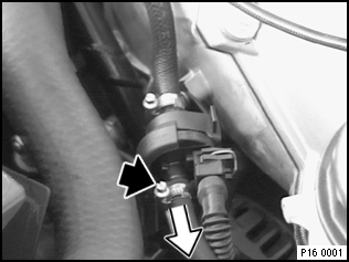
Tank ventilation valve |
|
To ensure fuel cannot flow out of the fuel tank via the expansion tank and the carbon canister when the vehicle is in an unusual position, a valve is installed in the expansion tank (rollover valve) which blocks the fuel connection when upside down.
The carbon canister prevents fuel vapours escaping through the tank ventilation line. The fuel vapours which collect in the carbon canister are drawn off via the tank ventilation valve and combusted. While the vapours are drawn off, the carbon canister is purged with the air drawn in.
The tank is connected with plastic pipes to the expansion tank and to the carbon canister to facilitate the fuel tank breather function.
The tank ventilation line (fuel vapour line in the case of system overpressure / purge line when fuel ventilation valve open) is the only open line in the fuel system. The line leads from the carbon canister and ends in front of the upper left tank half where it is secured with a plastic clip.